Tools
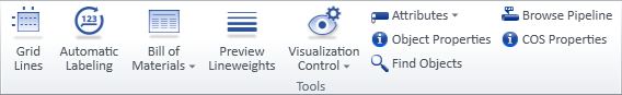
On the Home tab of the document editor, the Tools group contains some of the following tools, depending on active document type.
Grid lines

In drawing views, you can visualize the reference planes of the 3D model as a grid of named lines, and you can show dimensions from one grid line to another. Each drawing view manages its own grid, and you can change the visualization of each grid separately. Axonometric views can display only a single grid, whereas drawing views that are aligned with coordinate axes can include multiple grid line areas.
You can add grid lines to drawing views that are assigned to a page. You can also add and delete grids when the target view is not on the currently active page, but you cannot modify a grid unless you are on the respective page. When the drawing view contains similar markings created with legacy tools (Mark named XY-coordinates into view, Module lines into view), adding a grid prompts you to remove the old markings.
The grid lines are line entities that annotation tools on the Drafting tab can navigate to using 2D navigation commands. Drafting tools cannot modify grid lines, except for lines that you add and dimension manually.
You can use the tools in the Grid Lines dialog to adjust the positions of individual dimensions and text symbols within the grid, but be aware that all manual adjustments will be lost if the grid is regenerated. Actions that may cause grid regeneration include changing the scale or the limits of the drawing view, resizing the grid, and changing the grid properties. You cannot undo manual grid modifications, except by closing the document without saving.
When a drawing view has grids and the view is removed from the page, the grid is preserved: assigning the view to a page displays the grid again.
Prerequisites
-
Administrator has defined Coordinate references in the 3D model.
-
Administrator has defined Gridline Property Defaults and Axo Gridline Property Defaults to standardize grid configurations.
-
Administrator has defined Annotation Property Defaults to standardize grid visualization.
Do the following:
-
Select Home tab > Tools group > Grid lines.
-
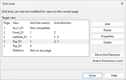
The Grid Lines dialog shows a list of drawing views in the open document. Views aligned with the coordinate axes have different settings from views that are not, such as axonometric views. The Grid line area(s) and Grid lines columns indicate whether drawing views already contain grid lines or whether grids cannot be added because the view is not on a page.
-
Use the following commands to manage grid lines for Views along coordinate axes:
-
Add – You can add grid lines to selected drawing views.
 Show/hide details
-
Select the drawing views from the list, and click Add. The Grid Line Properties dialog opens.
-
Define the Grid Line Properties as required, and click OK.
-
You are prompted if the view contains old module line or named XY-coordinate groups. Select Yes if you want them to be removed.
-
You are prompted if the grid area does not contain any reference lines in an axis direction that according to the grid properties should be shown. For more information, see No Reference Lines in Grid Area.
-
-
Resize – You can resize an existing grid when the drawing view is along the coordinate axes.
Show/hide details
-
Select a drawing view that has grid lines, and click Resize. The borders of all the grids in the view are shown, and there is a selection point in every corner.
-
To resize a grid, click one of its selection points, move the point to the new location, and click again to accept the move.
-
When you have moved all the points that you intended to move, press Enter to regenerate the grid.
-
You are prompted if the grid area does not contain any reference lines in an axis direction that according to the grid properties should be shown. For more information, see No Reference Lines in Grid Area.
-
-
Properties – You can change the properties of an existing grid.
Show/hide details
-
Select a drawing view that has grid lines, and click Properties.
-
If the view contains multiple grids, pick the one you want to edit and press Enter.
The Grid Line Properties dialog opens.
-
Define the Grid Line Properties as required.
-
Click OK to regenerate the grid.
-
You are prompted if the grid area does not contain any reference lines in an axis direction that according to the grid properties should be shown. For more information, see No Reference Lines in Grid Area.
-
-
Delete – You can delete all grids (as well as Automatic Dimensions based on those grids) from selected drawing views.
Show/hide details
-
Select the drawing views from the list.
-
Click Delete. The grids are removed.
-
-
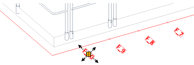
Move Grid Elements – You can move the individual elements of a grid, one dimension line or 2D symbol at a time.
Show/hide details
-
Select a drawing view that has grid lines, and click Move Grid Elements.
-
If the view contains multiple grids, pick the one you want to edit, and press Enter.
-
Move an element:
-
Click a dimension line or 2D symbol to show its selection point.
-
Click the selection point, and move the element to the new location.
-
Click to accept the move, and press Enter to complete the operation.
-
-
When you have moved all the elements that you intended to move, press Enter to return to the Grid Lines dialog.
-
-
Stretch Dimension Level – You can move the line-to-line dimensions of a grid when the drawing view is along the coordinate axes.
Show/hide details
-
Select a drawing view that has grid lines, and click Stretch Dimension Level.
-
If the view contains multiple grids, pick the one you want to edit, and press Enter.
-
Click one of the elements of the dimension to be adjusted, and do one of the following:
-
Drag the mouse to move all the connected dimension lines to the new location.
-
Select Modify set (P), click the dimension lines that should stay where they are, and press Enter to accept the set. Then drag the mouse to move only the included dimension lines to the new location.
-
-
Click to accept the move.
-
-
-
Use the following commands to manage grid lines for Other views:
-
Add – You can add grid lines to selected drawing views.
Show/hide details
-
Select the drawing views from the list, and click Add. The Grid Line Properties dialog opens.
-
Define the Grid Line Properties as required, and click OK.
-
You are prompted if the view contains old module line or named XY-coordinate groups. Select Yes if you want them to be removed.
-
You are prompted if the grid area does not contain any reference lines in an axis direction that according to the grid properties should be shown. For more information, see No Reference Lines in Grid Area.
-
-
Properties – You can change the properties of an existing grid.
Show/hide details
-
Select a drawing view that has grid lines, and click Properties.
-
Define the Grid Line Properties as required.
-
Click OK to regenerate the grid.
-
You are prompted if the grid area does not contain any reference lines in an axis direction that according to the grid properties should be shown. For more information, see No Reference Lines in Grid Area.
-
-
Delete – You can delete all grids (as well as Automatic Dimensions based on those grids) from selected drawing views.
Show/hide details
-
Select the drawing views from the list.
-
Click Delete. The grids are removed.
-
-
Move Grid Elements – You can move the individual elements of a grid, one dimension line or 2D symbol at a time.
Show/hide details
-
Select a drawing view that has grid lines, and click Move Grid Elements.
-
Move an element:
-
Click a dimension line or 2D symbol to show its selection point.
-
Click the selection point, and move the element to the new location.
-
Click to accept the move, and press Enter to complete the operation.
-
-
When you have moved all the elements that you intended to move, press Enter to return to the Grid Lines dialog.
-
-
-
Click Done.
Grid Line Properties
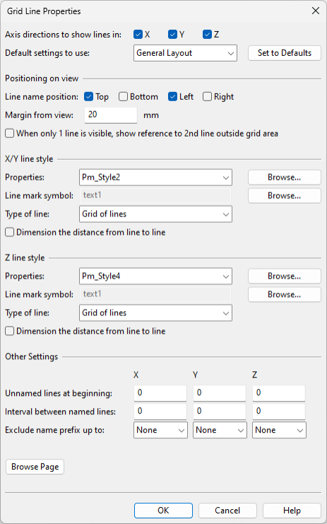
The Grid Line Properties dialog includes the following settings. Accepting the settings generates grid lines for the specified drawing views. By default, the grid area covers the view extents, with additional space added for line names and dimensions, if displayed. If you later add another grid to the same view, the new grid has slightly smaller extents.
Views along coordinate axes
These grid line properties are available for drawing views in the Views along coordinate axes category.
-
Axis directions to show lines in – Select the axis directions for which to add grid lines.
-
Default settings to use – Select the Gridline Property Defaults configuration to use for this grid. If you then edit the settings in this dialog, clicking Set to Defaults reloads the default settings from the selected configuration.
Positioning on view
-
Line name position – Select on which sides of the drawing to show the grid line markings (line names and line-to-line dimensions).
-
Margin from view – Specify whether to add a margin between the grid line markings and the view borders. Enter the value in millimeters; a negative value positions the grid markings within the view.
-
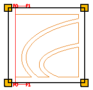
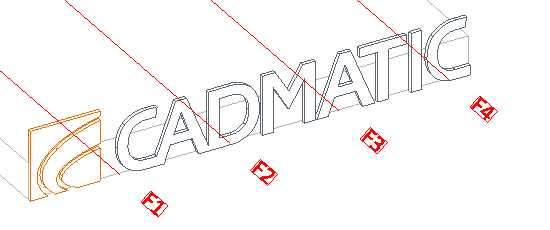
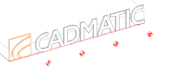
When only 1 line is visible, show… – If selected and the grid area only contains one reference line in X or Y direction, a special marking shows what is the next coordinate reference in that direction, if available. In the example below, only F0 is inside the grid area, so F1 is shown as the next available reference line.
X/Y line style, Z line style
-
Properties – Select the Annotation Property Defaults to use for this grid. The annotation properties define what the grid lines (Line Properties), the grid line names (Text Properties, Symbol Properties), and the line-to-line dimensions (Dimension Properties) look like.
-
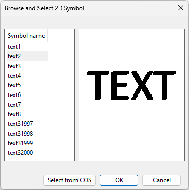
Line mark symbol – Select the 2D Symbol to use for displaying the names of the grid lines.

You can select one of the predefined 2D symbols or a custom symbol that has been stored in COS.
-
Type of line
-
Grid of lines – Select this option to display the grid as lines that extend across the view.
-
Comb(s) outside view area – Select this option to display comb-type reference line markings on the sides of the view. Every fifth line is slightly longer than the others.
-
Comb(s) – X on centerline if possible – Select this option to display a single X-direction comb along the centerline. If the (Y-direction) centerline is not within the view area, normal top/bottom combs outside the view area are displayed instead.
-
Line labels on outside – Select this option to only display a short line and the reference line's name for Z-direction reference lines.
-
-
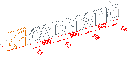
Dimension the distance from line to line – Select this option to display the dimensions between the grid lines, on the same side where the line names are displayed.
Other Settings
-
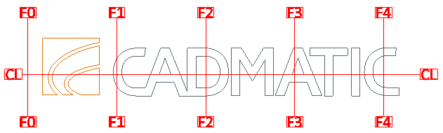
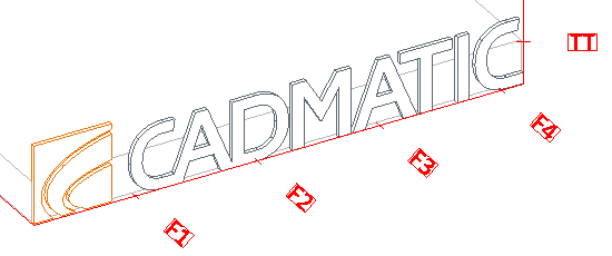
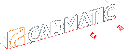
Unnamed lines at beginning X / Y / Z – This setting specifies how many grid lines are left unnamed starting from the first grid line in the grid layout. On a negative axis, the unnamed lines are the ones farthest from the origin.
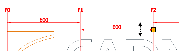
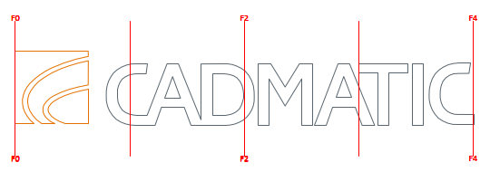
When the grid lies on a positive axis and covers the reference lines from F0 to F4, setting the value to 2 leaves F0 and F1 unnamed, as shown below.
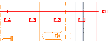
When the grid lies on a negative axis and covers the reference lines from F_4 to F0, setting the value to 2 leaves F_4 and F_3 unnamed.
Note: This is not available when adding a grid to multiple views at the same time. However, you can set this later, one view at a time.
-
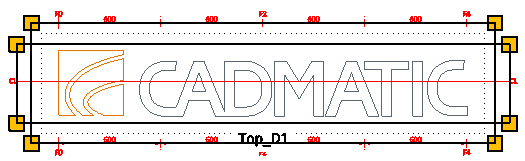
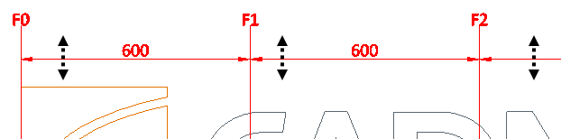
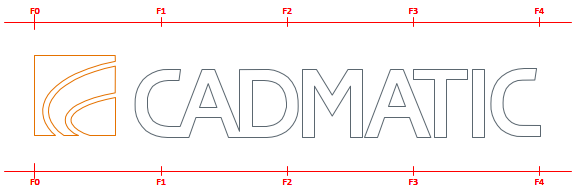
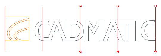
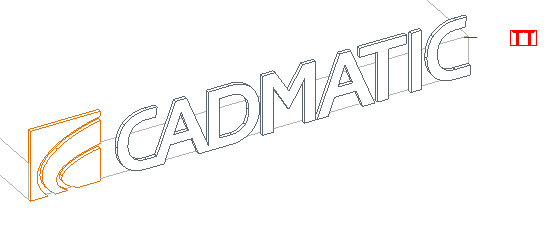
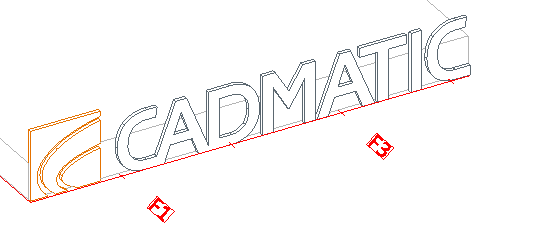
Interval between named lines X / Y / Z – This setting specifies how many grid lines are left unnamed after each named line. For example, if the value is set to 1, every other line is left unnamed, as shown below.
-
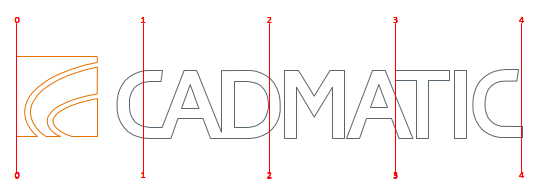
Exclude name prefix up to – You can use this setting to remove an unnecessary naming pattern from the beginning of reference line names, up to and including the first space character or a custom string. For example, setting this to Other: F would remove everything up to and including the F character, as shown below.
-
Browse Page – You can browse the active document page, for example, to see what kind of grids there are.
Other views
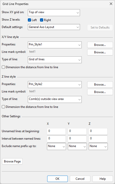
These grid line properties are available for drawing views in the Other views category.
-
Show XY grid on
-
Top of view – Select this option to draw XY lines at the top of the drawing view.
-
Top of view, closest Z-level – Select this option to draw XY lines at the highest Z-level inside view limits.
-
Bottom of view – Select this option to draw XY lines at the bottom of the drawing view.
-
Bottom of view, closest Z-level – Select this option to draw XY lines at the lowest Z-level inside view limits.
-
-
Show Z levels – Select whether to show Z-levels on the right and/or left side of the drawing view.
-
Default settings – Select the Axo Gridline Property Defaults configuration to use for this grid. If you then edit the settings in this dialog, clicking Set to Defaults reloads the default settings from the selected configuration.
X/Y line style, Z line style
-
Properties – Select the Annotation Property Defaults to use for this grid. The annotation properties define what the grid lines (Line Properties), the grid line names (Text Properties, Symbol Properties), and the line-to-line dimensions (Dimension Properties) look like.
-
Line mark symbol – Select the 2D Symbol to use for displaying the names of the grid lines.
You can select one of the predefined 2D symbols or a custom symbol that has been stored in COS.
-
Type of line
-
Grid of lines – Select this option to display the grid as lines that extend across the view.
-
Comb(s) outside view area – Select this option to display comb-type reference line markings on the sides of the view.
-
Line labels on outside – Select this option to only display a short line and the reference line's name for Z-direction reference lines.
-
-
Dimension the distance from line to line – Select this option to display the dimensions between the grid lines, on the same side where the line names are displayed.
Other Settings
-
Unnamed lines at beginning X / Y / Z – This setting specifies how many grid lines are left unnamed starting from the first grid line in the grid layout. On a negative axis, the unnamed lines are the ones farthest from the origin.
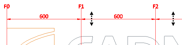
When the grid lies on a positive axis and covers the reference lines from F1 to F4, setting the value to 2 leaves F1 and F2 unnamed, as shown below.
When the grid lies on a negative axis and covers the reference lines from F_4 to F_1, setting the value to 2 leaves F_4 and F_3 unnamed.
Note: This option is not available when adding a grid to multiple views at the same time. However, you can set this later, one view at a time.
-
Interval between named lines X / Y / Z – This setting specifies how many grid lines are left unnamed after each named line. For example, if the value is set to 1, every other line is left unnamed, as shown below.
-
Exclude name prefix up to – You can use this setting to remove an unnecessary naming pattern from the beginning of reference line names, up to and including the first space character or a custom string. For example, setting this to Other: F would remove everything up to and including the F character, as shown below.
-
Browse Page – You can browse the active document page, for example, to see what kind of grids there are.
No Reference Lines in Grid Area
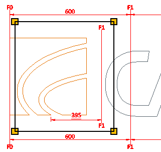
Normally, a grid shows reference lines that are located inside the extents of the grid area. If the grid area does not contain any reference lines, you can insert a virtual grid line that allows you to show the distance from a point inside the grid area to the nearest actual reference line. In this case, the distance value is underlined in the drawing.

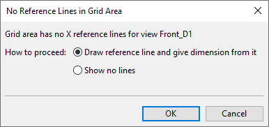
If you are defining a grid and the program does not find any reference lines from the grid area, the No Reference Lines in Grid Area dialog opens for selecting how to proceed.
-
Draw reference line and give dimension from it – Select this option to allow the drawing to show the nearest actual reference line outside the grid and how far it is from a user-defined point inside the grid. After clicking OK, do the following:
-
Start moving the cursor—the preview shows the name of the actual reference line currently nearest to the cursor's position—and pick the point where you want the virtual grid line to be placed.
-
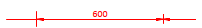
Start moving the cursor again, and pick the point to be dimensioned. A dimension line is drawn from the plane of the picked point to the virtual grid line, and an underlined dimension value shows the distance from the picked point to the actual reference line.
-
Start moving the cursor again, and pick the point where you want the dimension to be placed.
Note: Although these manually added grid lines are part of the grid, they also behave like normal 2D drafting objects. For example, they can be deleted with the Delete commands on the Drafting tab, and they are stored in a drafting object group, under the group type "ManualRefLineGroups", which you can manage with the Groups tools.
-
-
Show no lines – Select this option to not show any reference lines in the given direction.
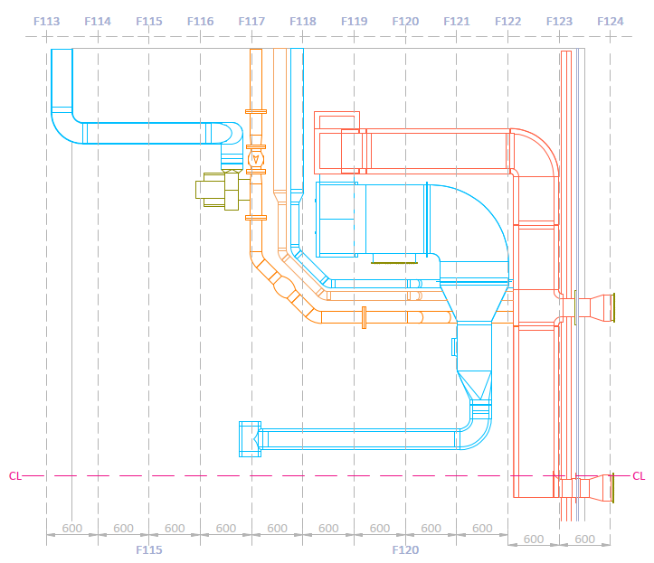
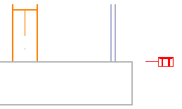
In the example below we can see two grids: one grid shows actual reference lines (F0, F1) while the other grid area is so small that there are no actual reference lines inside it. In the smaller grid area, the user has inserted a virtual grid line which shows that the nearest actual reference line is F1 and the user has dimensioned a point that is 395 mm from the actual F1 line.
Automatic dimensions

Select Home tab > Tools group > Automatic dimensions to open the Automatic Dimensions dialog, where you can run automatic dimensioning for any of the views in the open document. For details, see Automatic Dimensions.
Automatic labeling

Select Home tab > Tools group > Automatic labeling to open the Automatic Labeling dialog, where you can run automatic labeling for any of the views in the open document. For details, see Automatic Labeling.
Bill of materials

The Bill of Materials (BOM) is a group entity that contains the objects to include in material listings.
You can only create material listings and assign part numbers for objects that are members of a BOM group.
Note: To create a material list, the document must be using an ICGD that includes a material list. The ICGD is selected in Settings.
The name of the BOM group is "<name of drawing>.bom". Opening a document creates this group if it does not already exist. The program regenerates the m-file (the data for the bill of materials) and re-processes it whenever the BOM group has been modified.
The Bill of materials menu includes the following tools.
Manage BOM group | Add objects to BOM group | Remove objects from BOM group | Unlink objects from sister project | Generate all listings | Edit fields in BOM reports | Change part number | Manage reserved part numbers | Calculate surface area of BOM group
Manage BOM group
Select Home tab > Tools group > Manage BOM group to open the Manage BOM Group dialog, where you can manage which objects belong to the BOM group and unlink BOM objects from Sister Project Management. For details, see Manage BOM Group.
Add objects to BOM group
Select Home tab > Tools group > Add objects to BOM group to add objects to the BOM group by picking the objects from an open work view.
Remove objects from BOM group
Select Home tab > Tools group > Remove objects from BOM group to remove objects from the BOM group by picking the objects from an open work view.
Unlink objects from sister project
Select Home tab > Tools group > Unlink objects from sister project to remove objects from Sister Project Management. This command is available when editing a Plant Modeller drawing in a sister project target project and you have permission to perform unlinking. The command temporarily closes the document editor, opens a browser view that displays BOM objects linked to sister project management, and allows you to define the set of objects to unlink. After completing the selection, the document editor opens again.
Generate all listings
Select Home tab > Tools group > Generate all listings to update the bill of materials of the open document so that it matches the 3D model. If the ICGD of the document defines listings, this command saves them in the location defined in the General Drawing settings.
You must use this command if you have added part number labels or listings to the active document and then the 3D model has been modified.
Edit fields in BOM reports
Select Home tab > Tools group > Edit fields in BOM reports to edit the header fields of the ICGD. These fields appear in printed BOM reports.
Change part number
You can change or reset the part number of a model object that is shown in a drawing view on the active page.
Note: This tool does not assign a part number to an object that does not already have one. For more information on part numbers, see Managing part numbers.
Do the following:
-
Select Home tab > Tools group > Bill of materials > Change part number.
-
If there is more than one drawing view on the active page, click the drawing view containing the part.
-
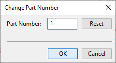
Select the part whose part number you want to manage, and press Enter. The Change Part Number dialog opens.
-
Do one of the following:
-
To change the part number, enter the new part number, and click OK.
-
To remove the part number from the document, click Reset.
If the object has a part number label in the selected view, the label is automatically updated/removed.
If the object has a part number label also in some other views, consider the following:
-
If associative annotations are enabled, you can update the other views one by one by starting to annotate them, as described in Updating associative annotations.
-
If associative annotations are disabled, the other views are not updated.
-
- You can select another object whose part number you want to change or remove, or press Esc to exit the tool.
-
Use Generate all listings to update the part numbers to the Bill of Materials.
Manage reserved part numbers
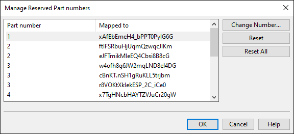
Select Home tab > Tools group > Manage reserved part numbers to open the Manage Reserved Part numbers dialog, where you can change or reset part numbers that are currently reserved in the active document. If you use this dialog to reset part numbers, closing the dialog prompts you to select whether to remove their labels from all drawing views.
Note: This tool does not assign a part number to an object that does not already have one. For more information on part numbers, see Managing part numbers.
-
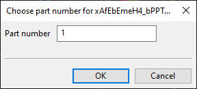
Change Number – Opens a dialog for entering a new part number.
-
Reset – Resets the selected mappings by removing the part number from them. If you reset all mappings that use the same part number, the part number is no longer reserved in the document.
-
Reset All – Resets all part number mappings. After this, there are no reserved part numbers in the document.
Calculate surface area of BOM group
Select Home tab > Tools group > Calculate surface area of BOM group to run a calculation that displays the total surface area of the BOM in the message pane.
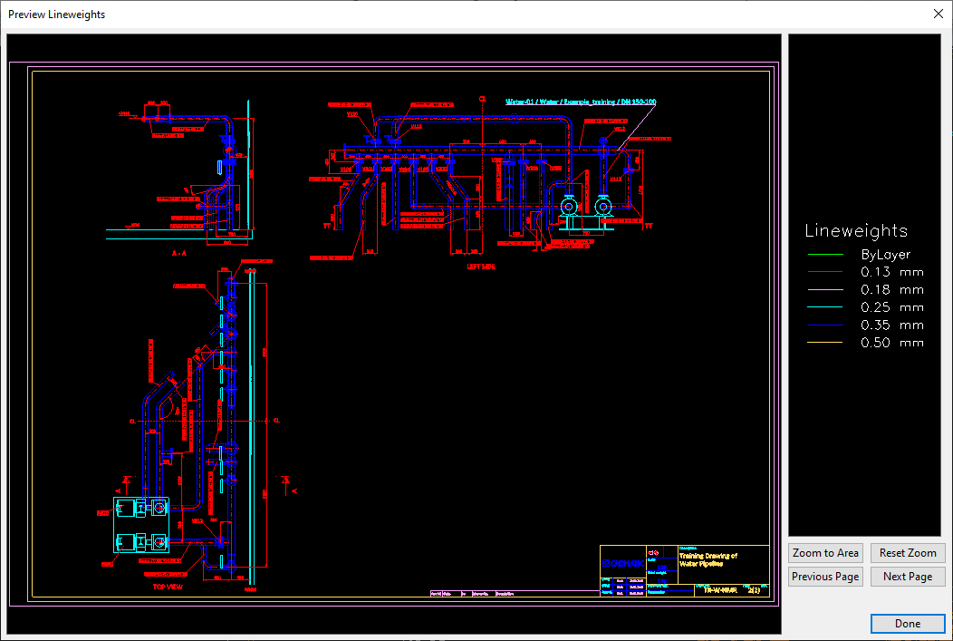
Preview lineweights

Select Home tab > Tools group > Preview lineweights to open a window that shows the active document page, with each lineweight in the drawing sheet and in the page and view annotations drawn in a different color. The right side of the window displays the color legend and these buttons:
-
Zoom to Area – Allows you to zoom the preview window to a specific area. Define the area to zoom to by picking one corner point and then the diagonally opposite corner point.
-
Reset Zoom – Restores the default zoom level to show the whole active page.
-
Previous Page, Next Page – Change the active page in the preview window and in the document editor.
Visualization control

The Visualization control menu includes tools for controlling the visualization of objects in drawing views.
When you use these commands, you may be prompted to specify whether the change should be applied to existing content rules or transparency rules. If you choose not to apply the change to existing rules, the change is implemented as an ad-hoc set, which is removed when the drawing views are fully regenerated.
Otherwise, these commands work similarly to the corresponding 3D work view commands:
Isometric view editor

The Isometric view editor button opens the Isometric view editor.
Note: This button is shown only if the active document is an isometric drawing or a pipe spool drawing.
Welds

The Welds button is displayed in the document editor toolbar if you opened the document from the Weld tab of Plant Modeller, as described in Edit. The Welds menu includes the following tools.
Create plan view | Manually label welds | Automatically label welds | Automatically label welds on perimeter
Create plan view
A plan view shows the welded objects from above. If there is a ceiling object in the viewing direction limiting the visibility to the welds, the view plane is automatically lowered below the ceiling object.
Creating a new weld document as described in Edit automatically adds a plan view to the document. If the plan view does not exist, you can create the view from Home tab > Tools group > Welds > Create plan view.
The line attribute style and the drafting style of the plan view are specified in the shared project settings, as described in Weld Drawing.
Manually label welds
You can manually add weld labels to welds that do not have a label in the given drawing view. You can place each label inside or outside the view, as appropriate.
Prerequisites
-
Project administrator has defined the labeling style in the shared project settings, as described in Weld Drawing.
-
You opened the document from the Weld tab of Plant Modeller, as described in Edit.
Do the following:
-
Select Home tab > Tools group > Welds > Manually label welds.
-
If there is more than one drawing view on the active page, click the drawing view to use, and press Enter.
-
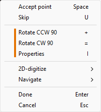
The program inserts a label to the first weld that has no label. You can now move and rotate the label, and you can modify the label text properties.
-
Press Space to accept the label or U to skip it. The next weld is automatically selected for labeling; continue this until all welds are processed.
-
You can use the tools in the Label menu or the general Modify tools to edit weld labels.
Automatically label welds
You can allow the program to add a label to all welds that currently have no label in the target view. Each label is placed close to the associated weld, and this labeling style is intended for views that contain a large number of welds.
You can repeat this process to incrementally add labels when new welds have been defined in the 3D model.
Prerequisites
-
Project administrator has defined the labeling style in the shared project settings, as described in Weld Drawing.
-
You opened the document from the Weld tab of Plant Modeller, as described in Edit.
-
The projection of the target view is such that the welds can be distinguished from the parts that they join.
Do the following:
-
Select Home tab > Tools group > Welds > Automatically label welds.
-
If there is more than one drawing view on the active page, click the drawing view to use, and press Enter.
-
The program runs automatic labeling for welds. You can use the tools in the Label menu or the general Modify tools to modify the labels.
Automatically label welds on perimeter
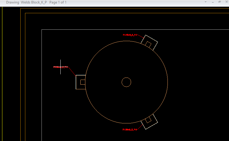
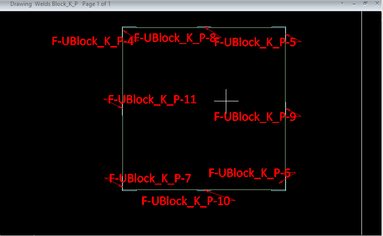
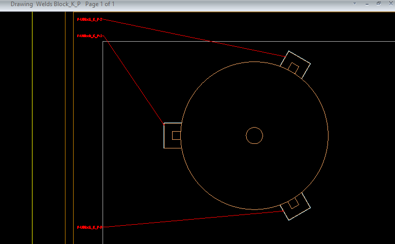
You can allow the program to add a label to all welds that currently have no label in the target view. Each label is placed in the sides of the view, and a reference line connects the label to the associated weld. This labeling style is intended for relatively small views that contain a relatively small number of welds. Otherwise, the reference lines might intersect with the other graphics in the view.
You cannot repeat this process to incrementally add labels—all labels should be generated as a single action.
Prerequisites
-
Project administrator has defined the labeling style in the shared project settings, as described in Weld Drawing.
-
You opened the document from the Weld tab of Plant Modeller, as described in Edit.
-
The projection of the target view is such that the welds can be distinguished from the parts that they join.
Do the following:
-
Select Home tab > Tools group > Welds > Automatically label welds on perimeter.
-
If there is more than one drawing view on the active page, click the drawing view to use.
-
The program runs automatic labeling for welds. You can use the tools in the Label menu or the general Modify tools to modify the labels.
Attributes

The Attributes menu includes the following tools.
Edit attributes | Multi-edit attributes | Edit cable node ID attributes | Show page header attributes
Edit attributes
Select Home tab > Tools group > Attributes > Edit attributes to edit the Plant Modeller attributes of model objects, as described in Edit.
Multi-edit attributes
Select Home tab > Tools group > Attributes > Multi-edit attributes to edit the Plant Modeller attributes of multiple model objects at the same time, as described in Multi-edit.
Edit cable node ID attributes
You can edit the Node ID of a cable network node.
Prerequisites
-
The cable network node is checked out to you.
-
An open Plant Modeller work view.
Do the following:
-
Select Home tab > Tools group > Attributes > Edit cable node ID attributes. The active Plant Modeller work view opens.
-
Select the cable way object that contains the cable network node and press Enter.
-
Select the cable network node and press Enter. A dialog opens, displaying the current Node ID.
-
Edit the Node ID value as required, and click OK.
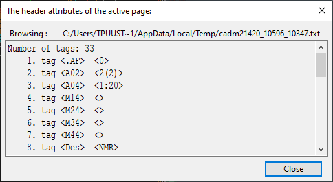
Show page header attributes
This command opens a dialog that shows the attributes stored in the page header.
Object properties

You can open the Object properties dialog for a model object in a drawing view.
Do the following:
-
Select Home tab > Tools group > Object properties.
-
If there is more than one drawing view on the active page, click the drawing view to use.
-
Select the object from the view, and press Enter. The Object Properties dialog opens.
Find objects

You can search for model objects based on key tags, any specific tag, COS object ID, or queries.
Do the following:
-
Select Home tab > Tools group > Find objects.
-
In the Find Objects dialog, define the search criteria as described in Find, and click Search.
-
Click Close.
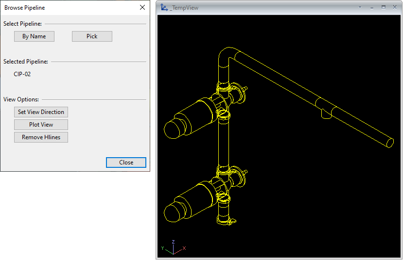
Browse pipeline

Select Home tab > Tools group > Browse pipeline to open the Browse Pipeline dialog, where you can select a pipeline that contains Standard Components and show the pipeline in a separate view.
You can select the intended pipeline from an object browser or pick it from one of the pipeline objects in a work view.
You can change the viewing direction, remove hidden lines from the view, and plot the view.
COS properties

You can open the COS Object Properties dialog for a model object in a drawing view.
Do the following:
-
Select Home tab > Tools group > COS properties.
-
If there is more than one drawing view on the active page, click the drawing view to use.
-
Select the object from the view, and press Enter. The COS Object Properties dialog opens.
